<< back to ETFD2
From: Randy C
Subject: Re: 3D printer question
Date: Sat, 16 Mar 2013 14:25:15 -0400
If you can output in STL, NetFabb's (netfabb.com) freeware version or their online service will convert it to OBJ. But I don't know of any printer than won't accept STL. IGES and STEP are almost certainly non-starters. They're proprietary formats, so including support for them means having to pay a license fee. But the usual workflow is to output the final model for "slicing" (if 3D printing) or for toolpath generation (if milling) in STL. If you can output STL, you should be set.
Note that there's a lot more to designing a part for a printer than just getting the shape right. Model files have to be "manifold", meaning all polygons in the model have to share exactly one edge and only one edge with their adjacent polys. Many CAD constructive solid geometry operations that are used to cut holes leave extra vertices, flipped faces, double faces, or split edges (non-manifold) that require cleanup. Also, unlike when you model for subtractive processes like milling, the additive prototyping process also requires the model files be water-tight. NetFabb is a great program to use on your geometry to make sure it meets the necessary requirements, and is also able (in the freeware case) to be able to repair many common problems so you don't have to go back to your CAD software and fix it there (which can be challenging for a complicated piece of geometry). Their paid version has more advanced features, but my view is that if my model is busted enough I'd need those features to fix it, I'm better off going back to the source geometry to fix it there anyway. There's no excuse for overly slopping modeling, I say!
I use software called "Lightwave3D" for my modeling. It's really for CGI not CAD. Most of what I do doesn't have to be precise enough I need hard-core CAD features. It does have a parametric plugin for doing "real" work, but I rarely employ it. I can "freehand" down to a 10th of a mm, which is good enough for 99% of what I make. My workflow is to build my model in Lightwave which is an LWO file. I output a fully triangulated mesh in OBJ and import in to NetFabb to check the geometry for errors. Load in to NetFabb, analyze and have it repair as necessary (sometimes NetFabb makes the wrong choices and I have to go back to Lightwave to figure out and fix the problem, but most of the time NetFabb does a great job of fixing minor stupid errors). Then I export from NetFabb to STL and import that in to my printer's CAM software, "ReplicatorG". I position the model on the build platform, enter information on the filament I'm using, make some choices about whether I need "supports" (artifacts have to be constructed to support overhanging features or the printer prints on air when it gets to the overhang, the print fails), and then "slice" the model. The slicing operation generates the toolpath for my printer (it "knows" what kind of printer I have and how its mechanics operate) and outputs gCode. Then, Replicator converts the gCode to "SG3" format, which is binary, which is what my printer actually processes. Load that file on the printer, align the print head and build platform, hit "start" and come back in a while to pry off the finished results like you see, below.
My printer is a MakerBot Replicator1 dual-head. It's not that accurate anyway, so Lightwave is really more than you need. I also have a Taig CNC which is quite a bit more accurate, but Lightwave works good enough there too. I'm not fabricating racing engines or anything.
![[]](pic/image0032.jpg)
From: Randy C
Subject: Re: 3D printer question
Date: Wed, 27 Mar 2013 22:06:50 -0400
These concept things took me a while to figure out. Rather than send
you down the same laborious path I went down (which involved a fair
amount of reading, believe you me), let me attempt to distill it.
The concept of water-tight is straightforward.
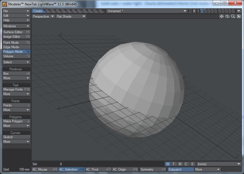
This Sphere is water tight. It has an outside and an inside and there
is no way to get from one to the other without drilling a hole through
one of the faces. All the faces are arranged with the same �normal�
(the face fronts are all pointed outward). You cannot draw a line from
the front of a face that will be able to reach the back of the face.
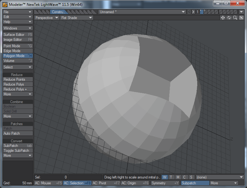
This Sphere with a cube subtracted out of it is also water tight. The
pocket I removed from the top of the sphere is still fully connected to
the �outside�. The same rule applies. Pick any polygon face you can
see and you will not be able to trace a line that will reach the back
side of that face without penetrating another face.
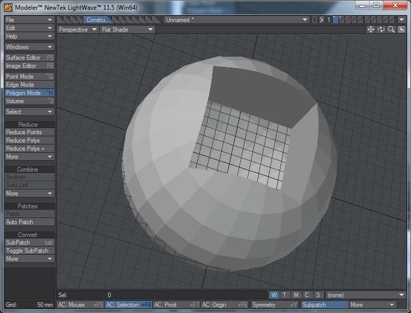
But if I delete the face at the bottom of the pocket, now you *can*
reach the back of an outward facing polygon by drawing a line across
the other faces. This object is not water tight and cannot be printed
(the polygons that make up the faces have zero thickness, which makes
them unprintable. In the water tight case the polys are still zero
thickness, but because there�s no way to reach the �inside� from the
�outside� the CAM software will treat the interior as solid (even
though it�s modeled as a hollow).
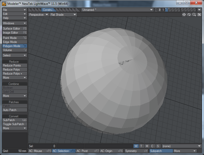
By way of a less overt example, consider this sphere where I�ve Removed
one polygon (top left), making the interior accessible from the outside.
The errors that make an object not water tight can be subtle. This
same kind of problem occurs in subtractive processes like milling, but
CAM software for those systems (I have a 4-axis CNC as well as a 3D
Printer) ignores gaps too small for the chosen tool to fit in to. For
additive processes like printing, the CAM software must be able to
clearly distinguish between the inside and outside, no gaps are
allowed.
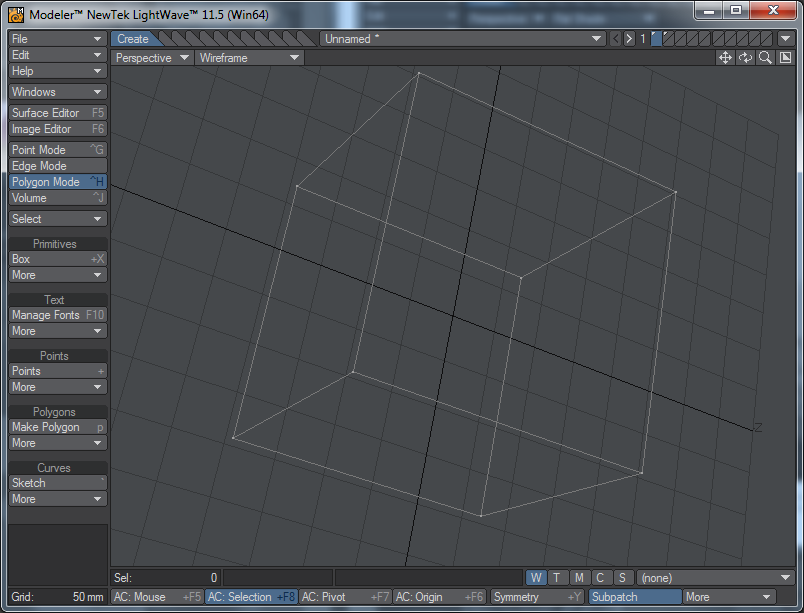
Manifold is trickier. Consider this cube in line drawing. A polygon
edge is defined as the line between two and only two vertices. In this
Image each of the 6 faces (polys) shares an edge with exactly one other
face. This object is �manifold� because of it (it�s also water tight).
The edges are common, meaning that while each polygon is unique, the vertices at each corner are not. They are shared with the
polygons on the adjacent sides. There are six faces of four vertices each, but there are not 24 vertices, there are only 8.
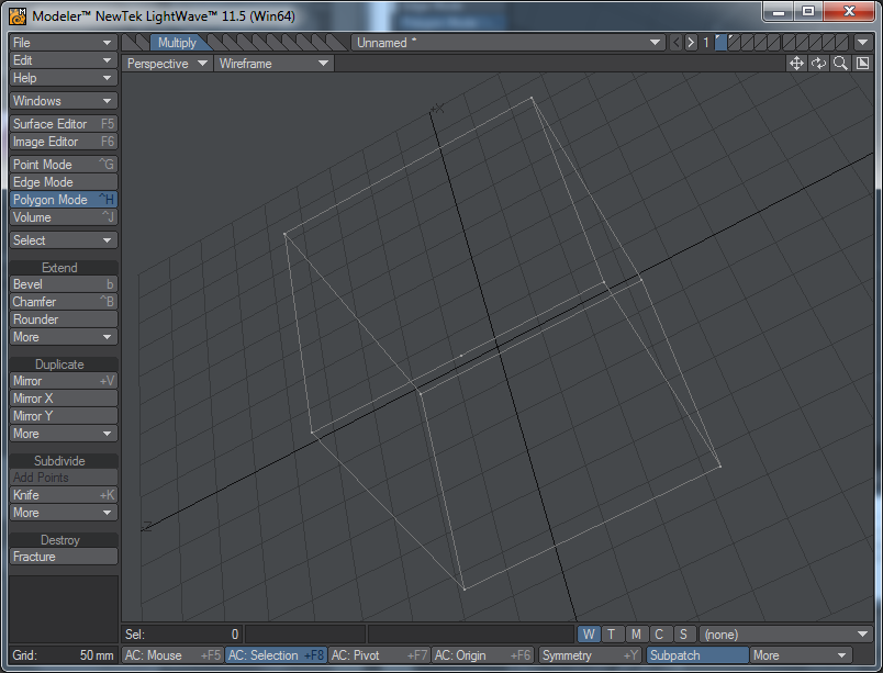
In this next image, you�ll notice I�ve added a point (vertex) midway
along the front edge of the top face of the cube. The single long
edge is now considered to be two smaller edges. That additional vertex
is an endpoint for a new left and right side where the original
edge used to be. This object might or might not be manifold. You
can�t tell from this image. If that point that was added is shared
by both polygons that abut along the edge, the object is OK. But if I
only added the point to one of the faces (in this case, the top)
then the front face�s top edge has two vertices while the top face�s
front is actually two edges joined at a common vertex in the center.
See next picture for an illustration of this key detail.
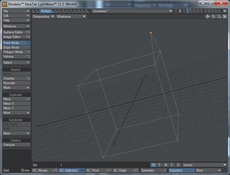
I rotated the cube to make it easier to see that I�ve moved that
additional vertex up in the Y axis. Now you can clearly see that the
top face�s edge has an extra point that the adjoining front face did
not. When the extra vertex was on the same line connecting the
two corner vertices it was not obvious that the error was there, the
object would still have been water tight but it was not manifold.
After moving the vertex up, the object is not water tight but it is
manifold. But the top polygon is no longer planar, which will cause
other Issues with the CAM software.
It�s a bit easier to see as a solid wireframe shaded image. Here, I�ve
told my software to �triple� the non-planar surface, which fixes
The non-planarity problem (but not necessarily the way I�d have wanted
the surface to be broken up). But as you can see, there is
still an opening from the inside to the outside. This object is manifold but not water tight.
![[]](pic/image009.png)
Constructive Solid Geometry tools tend to leave extra points on edges
all over the place. The errors can be very difficult to find even
once you learn what to look for. I still make mistakes. So when I�m
designing a new object, I�ll periodically move to NetFabb and check
it for errors. The more detail you work in to the model, the harder it
is to find the errors, and NetFabb is imperfect, it can make the
wrong choices about what needs to be fixed when there are many possible
solutions to the errors, and the likelihood of that increases
as the complexity of the model increases unless you periodically stop to check for and correct errors.
Programs like SolidWorks should be much better about this than my
Lightwave software, but I don�t think they�re perfect. I seem to
see cases where people who use more expensive �real� CAD software (Lightwave is designed for animation and graphics, not CAD)
still recommend NetFabb as if they�re using it themselves.
<< back to ETFD2